

NO FIRE – Fire and environmental protection system in the tunnels
BRIEF DESCRIPTION
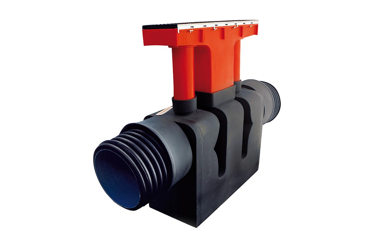
NO FIRE is the system implemented in the collection of liquids that could be found on the road surfaces of tunnels.
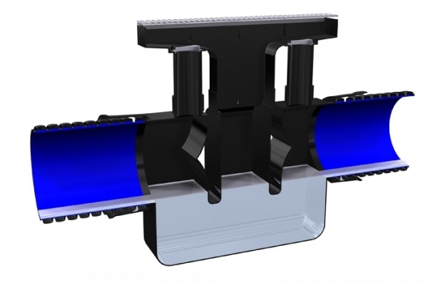
It has a dual purpose: protects the environment from accidental spilled liquids and reduces the potential fire spread through the manifold.
The system consists of several units: NO FIRE storm drains made of two siphons (with a drain grid D400 load class) + standard PP corrugated pipes (other can be used on request) + water treatment system.
The NO FIRE system was designed and developed to satisfy all safety standards (in terms of personal and environment) requested by recent road tunnels, the planned ones and the ones that will be upgraded.
MAIN FEATURES & BENEFITS
Safe and tested system;
In conformity with the security standards requested by TERN networks;
Multiple sizes available, for pipes with DN/OD 250-315-400 mm and DN/OD 300-400 mm;
Gravity system (no electromechanical devices);
Environmental safety in case of fire (no fire and smokes spread in the manifold);
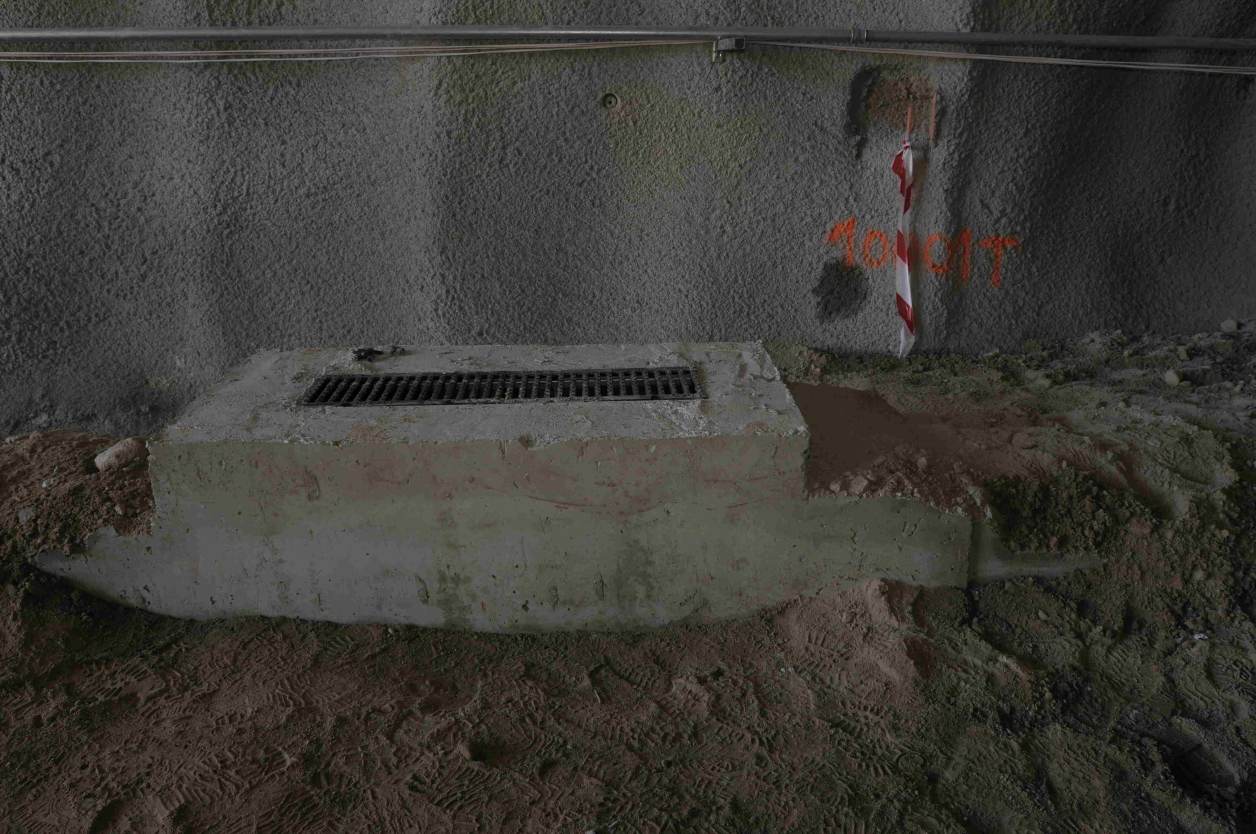
Surface drainage channel: 500 x 270 mm;
Lightweight and ease of installation;
Durability: a cement mortar coating guarantees the functioning of the system in case of fire too;
High chemical and abrasion resistance;
Inert to stray currents;
Excellent benefit-cost ratio;
Full technical support by the U. T. System Group.
COMPOSITION
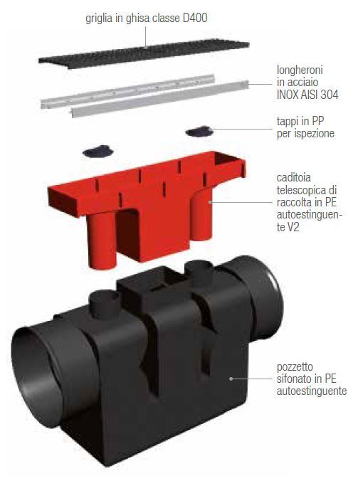
The NO FIRE gully is made of polyethylene (PE) with a V2 flame resistance rating (UL94).
UPPER BODY
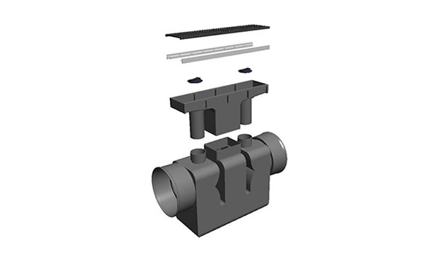
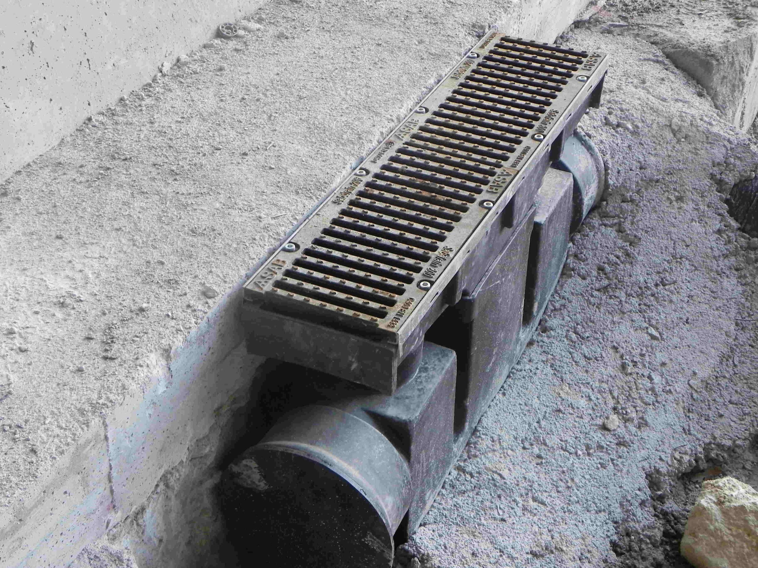
Features a cast iron grate (traffic-rated D 400) and a liquid collection tray with three vertical outlets: a central square outlet directs liquids into the underlying reservoir, while two outer circular outlets (sealed with screw caps and gaskets) allow for system inspection and maintenance near the pipe inlets. The outlet extensions can be easily cut to adjust their height according to installation requirements.
LOWER BODY
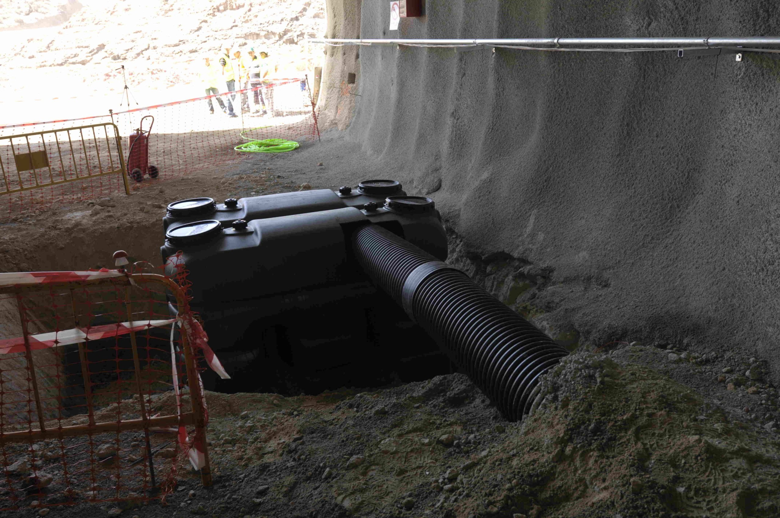
Consists of a reservoir featuring three upper sockets with gaskets for connection to the three extensions from the upper body. These extensions connect to the reservoir at three points separated by two vertical partitions; these divide the reservoir into three sections while sharing a common bottom, creating a DOUBLE-TRAP system (containing water) that prevents air entry while allowing the flow of liquids. Connection sockets for the collector (standard corrugated piping) are located on both sides of the reservoir.
This post is also available in:
